Arduino Midi Input
There's some confusion on the internet how to wire old style 5-pin midi input to Arduino. My main concern is the optocoupler on the midi input. It's often wrong type. Let's see how to do this properly.
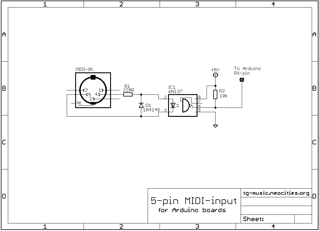 Let's start with the midi input. As we can see in the schematic, this is very simple circuit. Two resistors, diode, optocoupler and a connector. On the left side is the connector. This is five-pin DIN connector. To be more precise it's five-pin female 180° DIN connector. As one would guess, there are several five-pin DIN connectors, like 240° but what we want for midi is 180°. And one important note: pin two is grounded only on the output connector!
Next, we have 220Ω series resistor for the optocoupler LED. Optocouplers usually have very robust LEDs, but you don't wanna burn one out. And then we have the most common small signal diode 1N4148 parallel with the optocoupler LED. This is because if we have AC-signal input to optocoupler, we need it to protect the LED from breaking down due to reverse polarity.
And now the main course: the optocoupler. The most misunderstood component in the whole thing. Do not use 4N25 or other similar devices often used in Arduino circuits. These are not fast enough. Midi standard states that rise and fall times must be shorter than 2μs when we drive the LED with 5mA. Recommended optocouplers are Sharp PC-900 (or H11L1). So why would I use 6N137? Because it has logic output, and it's CMOS compatible. It's also way fast enough and super simple to use. Robust, reliable and inexpensive.
Sure, you can use 4N25 or any other opto and add circuitry to it to make it "work", or you can just get the right components in the first place. Don't just blindly copy some random schematic or Fritzing drawing from the instructables. And if you are still unsure, study the midi standard yourself.