1Hz timebase with CMOS
Every clock requires a solid 1Hz timebase. This can be almost anything between machanical pendulum and atom clock. For simple digital clocks and other timing projects easy and inexpensive options are available. I'll show you three different methods with my favourite 4000-series CMOS ICs.
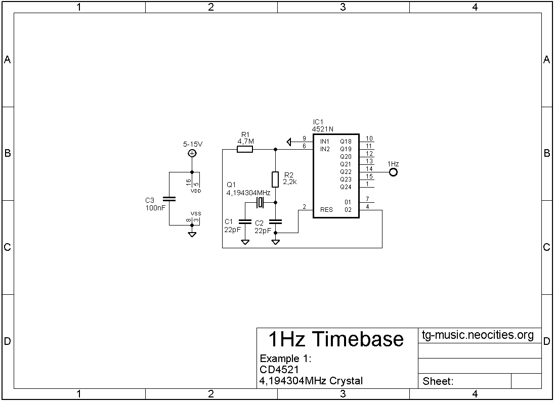
CD4521 and 4,194304MHz crystal
 First example is made with CD4521 24-stage frequency divider. This is super simple one IC solution. 4,194304MHz crystal oscillator and output from Q22 (pin 14.) has a 1Hz square wave. Capacitor C2 can be trimmer for frequency adjustment. While this is very simple circuit, I can see at least two downsides. This is relatively high frequency circuit, and might need some attention when in practical use. Other problem might be the crystal. It's not the most common value, and definitely not as common or inexpensive as 32768Hz clock crystal.
Benefits are in it's versatility. You can get 0,25Hz, 0,5Hz, 1Hz, 2Hz, 4Hz, 8Hz and 16Hz divisions out of one IC at the same time with no modifications to schematic shown here. And talking about modifications, you can replace one 22pF capacitor with trimmer capacitor (4-40pF for example) and fine tune the frequency.
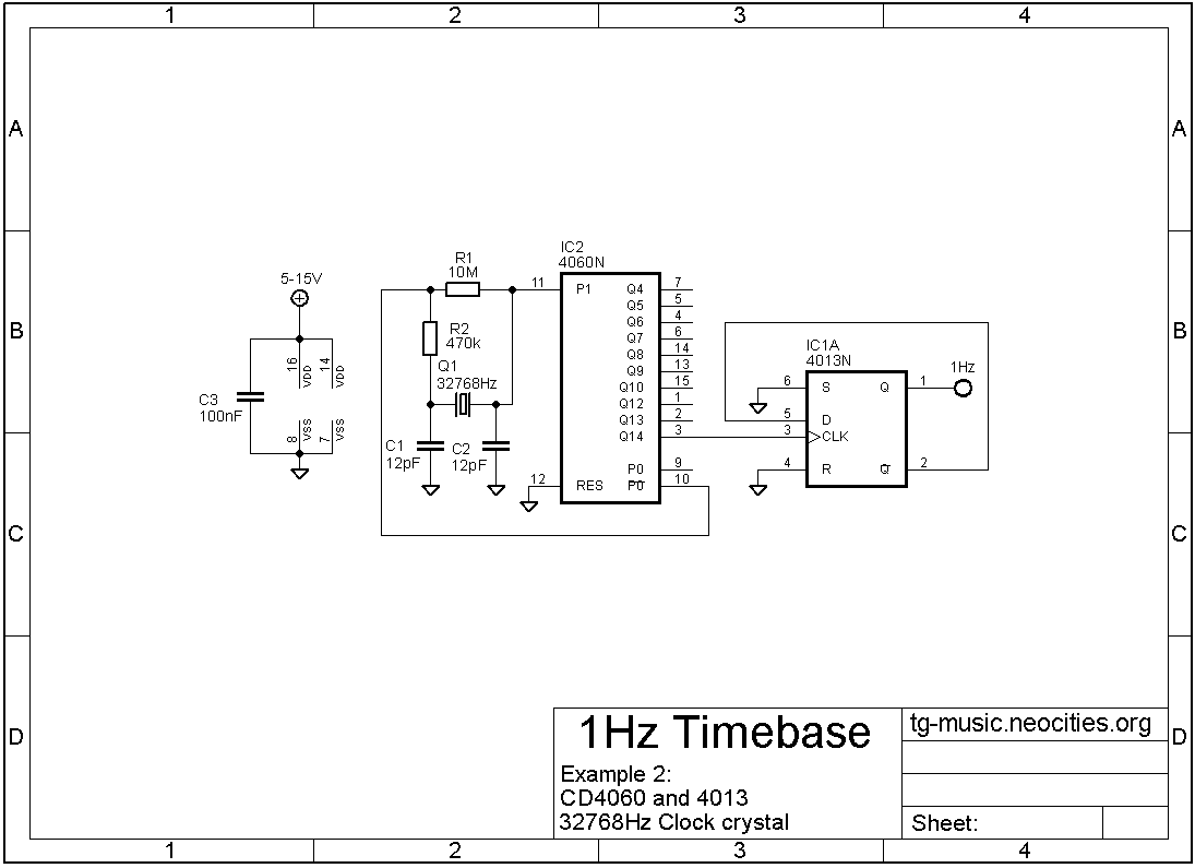
32768Hz clock crystal
 This version uses very common 32768Hz clock crystal. These crystals are inexpensive and widely available. CD4060 is 14-stage counter/divider and oscillator. Very useful IC. But we can only get 2Hz output from CD4060. So we need to divede our 2Hz one more time to get down to 1Hz. This is easy to do with CD4013 dual D-type flip/flop IC. In fact since CD4013 is dual flip/flop, so we could divide 1Hz down to 0,5Hz without any additional components.
This circuit takes a bigger footprint on PCB since it uses two ICs, one with 14 and other with 16 pins. Might not be a problem, but one thing to consider. For 4000-series CMOS current consumption is relatively small and usually not a problem. Clock crystals vary in quality and some are not very accurate at all. Be sure to use right value load capacitors for your specific crystal (12pF in my example). You can also use external 32768Hz clock connected to CD4060 pin 11. This could be for example DS3231 RTC IC. It has very accurate 32768Hz output. Even on counterfeit chinese ones.
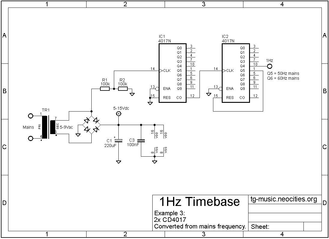
1Hz from mains frequency
 Do you have an old clock radio? If you do, there's a good change this is how it keeps time. In this last example we use two CD4017 decade counter/divider ICs. In CD4017 pin 12. is "carry out" and it will divide anything that goes to clock input (pin 14.) by ten. So after first CD4017 we have 5Hz square wave coming from pin 12. Second CD4017 will divide this 5Hz by five since reset pin is connected to Q5. If your country has 60Hz mains frequency, use Q6 for reset.
Mains frequency is very accurate for our use. It is compensated in the long term, so even if it's slow now it will be slightly fast later. It'll average out. In Finland we use SFS-EN 50160 standard for mains frequency. It states that mains frequency must be within ±1% at 99,5% of the time and within +4% / -6% at 100% of the time.
You should never take the frequency reference directly from wall socket. You can use any small(ish) transformer between 3-9VAC. You can rectify that and use the DC-voltage to power rest of your circuit. You don't want to get electric shock. You can die and it will hurt the whole time you're dying.
