Electronics Today Nanoamp Meter 7/1981
Sometimes measuring tiny currents is a necessity, and since my Advance Instruments Alpha II decided to retire itself I had to build something to replace it. A little browsing on the worldradiohistory.com and I found this meter. This looks simple, good and perfect for my use.
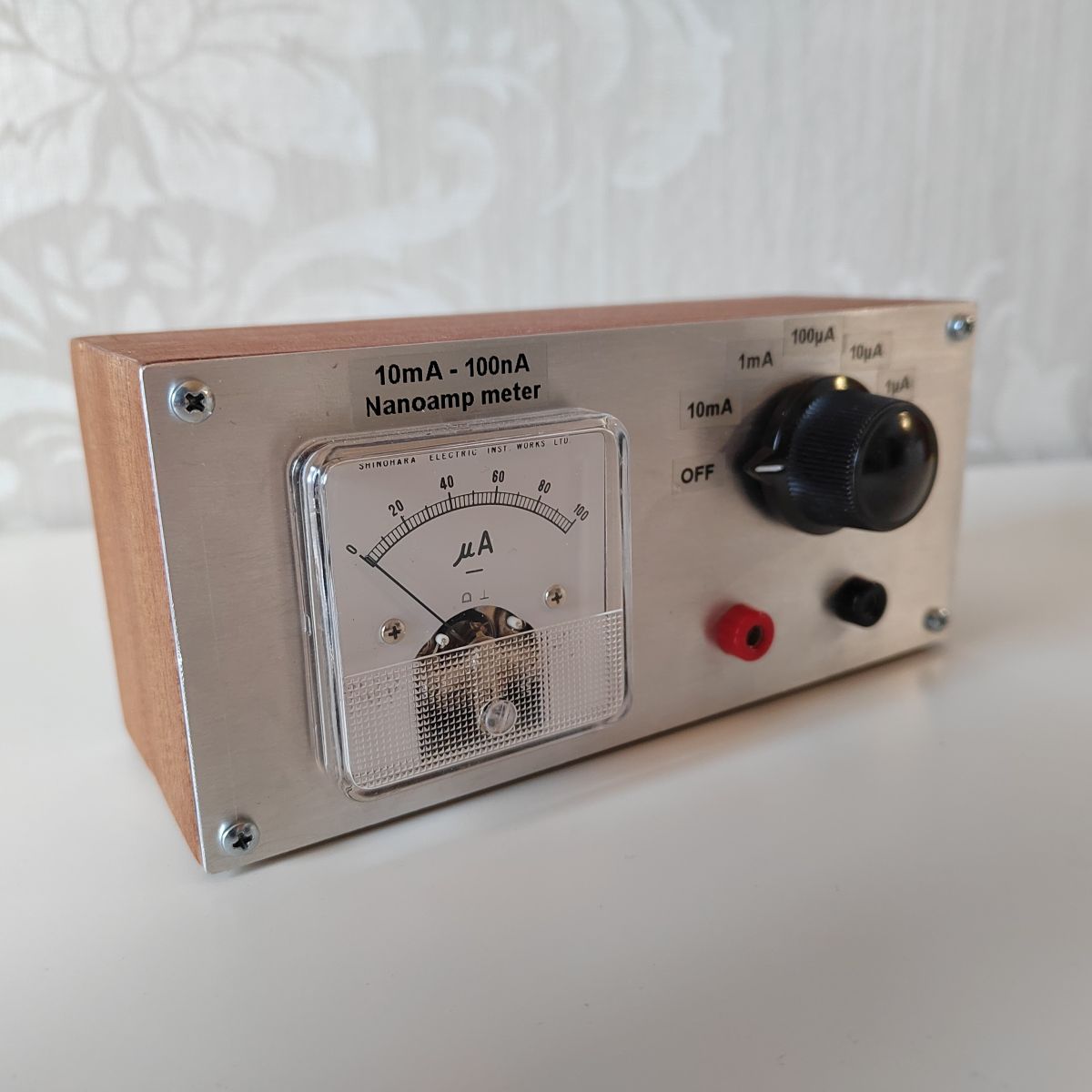
My first idea was to modify this meter to have a digital readout. This would be relatively simple to do with Arduino or something like that. However since I had an unused very good quality Japanese Shinohara 100μA panel meter I decided to use that, just like in the original article. Modern made in china meters are often very poor quality, nonlinear and inaccurate so if you have to use one of those... Just be aware of that.
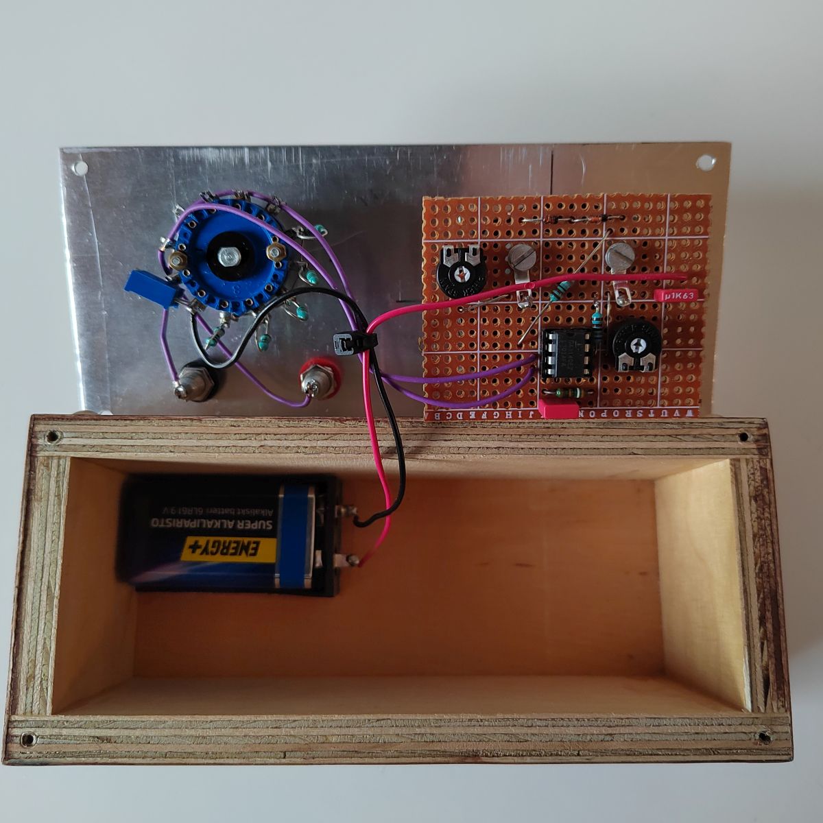
Another thing to be aware is resistor tolerances. All resistors should be minimum of 1% tolerance. Modern metal film resistors are good for this and those are often even better that 1%. You could use an accurate (has to be better than 1% accuracy) multimeter to select closest values. But anyway, 1% is often just fine. And if you want 0,1% resistors Vishay/Dale CMF-series is a good choise. I used a 10-turn 10R trimmer for R2 to compensate some wire, switch and solder joint resistances. OP-amp should be high input impedance type. Just use CA3140, it's still available (as of 8/2022 price is getting very high). I build mine on small piece of perfboard. Proper PCB would have been better, but it's not requirement at all. I would also recommend a better-quality rotary switch, mine is recycled and very old. Anything more modern will work fine here.
 Calibration is easy but tedious. You need a good, solid and accurate 10 volts power supply and some 1% resistors. Use a good quality lab power supply and/or accurate multimeter to get exactly 10 volts dc. Now we can use ohms law to make some measurements. For example, for 1mA current: measure it across 10kΩ/1% resistor and adjust R11 for full scale deflection. This will work because I=U/R (current is voltage diveded by resistance). If everything goes well, your meter is now calibrated. In reality you need to adjust RV1 too. Original article makes this simple, but in reality, you might need to readjust both RV1 and R11 several times to get the meter as accurate as possible. When you get the one range to show correctly, other ranges will be correct as well. My only problem was with R2 (1Ω) because some wires, switch contacts or something added tiny bit of resistance to it. Use multi turn trimmer here to get exactly 1Ω.
Very few old-style instruments are usefull today, but nanoamp meter is an exception. Today electronic devices use less and less current and modern reasonably priced multi meters can't measure anything below 1mA (if that). For example you can put ATMega328 into deep sleep power saving mode, and in that mode it uses only 0,36mA (360μA) of current. Standby mode uses 0,84mA (840μA). And ATTiny85 in deep sleep mode will need less than 10μA!
These are of course rough examples, but you get the idea. And don't be afraid of the analog meter. It's very easy and quick to read when you get used to it. This is relatively inexpensive solution to a problem that surprisingly still exists, and you can make it look cool while you are solving it!
Read the original article here (pdf)